How Wet riser system diagram can help you in Firefighting design?
In the event of a fire, having the right firefighting tools and systems in place can make all the difference in the safety of your building occupants and the property itself. One of the most important components of any firefighting design drawing is the wet riser system diagram.
A wet riser system is a network of pipes, valves, and pumps that are installed between the water supply and the firefighting outlets such as fire hydrants and sprinklers. The system is designed to provide a steady flow of water to the outlets at a constant pressure so that they can be used effectively in the event of a fire.
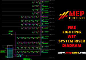
The wet riser system diagram is an important tool in designing a firefighting system. It shows the layout of the system and the various components that make it up. For example, the diagram will show the location of the water supply, the pumps, and the various valves and outlets. Additionally, it will show the layout of the pipes that connect the various components and how they should be connected.
The wet riser system diagram can also be used to identify any potential problems and suggest solutions. For example, if the pipes are not connected correctly, the system may not be able to provide enough water pressure to the outlets. The diagram can also help to identify any potential blockages in the system. The wet riser system diagram is an invaluable tool in designing a firefighting system. By looking at the diagram, you can quickly identify any potential problems and take steps to ensure that the system is working correctly. This can help to ensure that the system is able to provide effective firefighting in the event of an emergency.
Read also: AutoCAD HVAC Blocks

Download from Here: DOWNLOAD WET RISER SYSTEM DIAGRAM IN AUTOCAD DRAWING
How a firefighting riser diagram can solve your drawing problems
Firefighting riser diagrams are a great way to solve drawing problems and make sure that your fire protection system is compliant with regulations. They provide an easy way to understand the design and layout of the fire protection system, allowing for quick identification of potential issues. Riser diagrams are particularly useful in high-rise buildings, where the complexity of the system can be difficult to manage.
Riser diagrams are typically created using computer-aided design (CAD) software. This allows for easy manipulation and modification of the diagram, making it easier to ensure that all components are located in the correct places. The diagrams will usually consist of a series of lines, representing the pipes, valves, and other components that are used to ensure that the system is functioning correctly.


